
 logo
logo - Home
- Product
- News
- Solutionlist
- About Us
- Contact Us
Release Time : Jul-01-2021
Any electronic or electrical control panel may require wiring. Whether the application is for consumer equipment, commercial equipment, or industrial systems, designers need to choose reliable products that are easy to install and can operate reliably for many years. Terminal blocks meet these requirements and are the most common way to interface electric field lines with panel-mounted electronic and power systems.
The most common and traditional screw-type single-layer terminal is a simple solution, but it is not always the most efficient use of space or labor. Especially when people consider that many wires are installed in the form of functional pairs or three-wire groups, multi-level terminals obviously have design advantages. In addition, newer spring-type mechanisms are more reliable and easier to install than screw-type products. When selecting terminal blocks for any application, designers should consider form factors and other product characteristics to obtain the best performance.
Basic knowledge of terminal blocks
The basic terminal block consists of an insulating shell (usually some form of plastic), which can be installed on a DIN rail that conforms to industry standards or directly bolted to the back plate inside the shell. For compact DIN terminal blocks, the housing is usually open on one side. These blocks are designed to be stacked together to maximize space savings, and only one end of the stack requires an end cap(Figure 1).
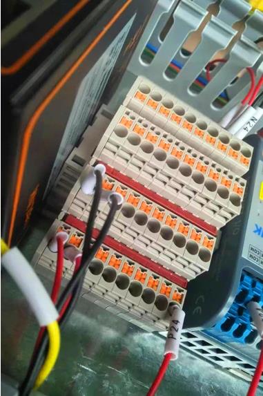
1. The DIN-type stackable terminal block is a compact and reliable way for industrial-grade wiring connections.
“Feedthrough” terminals usually have a wire connection point on each side, and a conductive strip between these two points. Traditional terminal blocks can only handle one circuit each, but newer designs can have multiple levels and may also include convenient cable shielding grounding devices.
The classic wire connection point is a screw, and sometimes a washer is used. The wire needs to crimp a ring or U-shaped lug at the end, then install it and tighten it under the screw. The alternative design incorporates the screw connection of the terminal block into the cage clamp, so that the bare wire or the wire with a simple cylindrical ferrule crimped on the end can be directly installed in the cage clamp and fixed.
A recent development is the spring-loaded connection point, which completely eliminates screws. Early designs required the use of a tool to push the spring down, which would open the connection point so that the wire can be inserted. The spring design not only allows faster wiring than standard screw-type components, but the constant spring pressure also resists vibration better than screw-type terminals.
An improvement to this spring cage design is called push-in design (PID), which allows solid wires or ferrule crimped wires to be pushed directly into the junction box without tools. For PID terminal blocks, simple tools can be used to loosen the wires or install bare stranded wires. The spring-loaded design can reduce wiring work by at least 50%.
There are also some common and useful terminal accessories. The plug-in bridging bar can be inserted quickly, and multiple terminals can be cross-connected at a time, providing a compact power distribution method. Marking regulations are very important to provide clear identification for each terminal block conductor, and spacers allow designers to provide a significant way to isolate one or more terminal blocks from each other. Some terminal blocks integrate a fuse or disconnect device inside the terminal block, so no additional components are required to perform this function.
Keep circuit grouping
For control and automation panels, power distribution circuits (whether 24 V DC or up to 240 V AC) usually require two wires. Signal applications, such as connections to sensors, are usually 2-wire or 3-wire, and may require additional analog signal shield connections.
Of course, all of these wiring can be installed on many single-layer terminals. However, stacking all the connections of a given circuit into a multi-level junction box has many initial and ongoing benefits (Figure 2).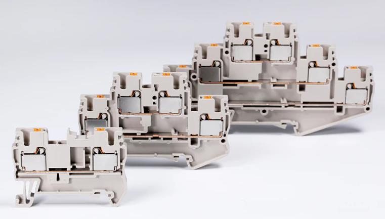
2. Dinkle DP series terminal blocks provide various sizes of single-layer, two-layer and three-layer shapes.
The multiple conductors that make up a circuit, especially analog signals, usually run in a multi-conductor cable, rather than as separate conductors. Because they are already combined in one cable, it makes sense to terminate all of these related conductors to one multi-level terminal instead of several single-level terminals. Multi-level terminals can speed up installation, and because all conductors are close together, personnel can more easily troubleshoot any problems (Figure 3)
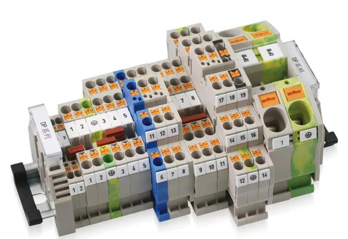
3. Designers can choose the best terminal blocks for all aspects of their applications. Multi-level terminal blocks can save a lot of control panel space and make installation and troubleshooting more convenient.
One possible disadvantage of multi-level terminals is that they are too small to work with the multiple conductors involved. As long as the physical dimensions are balanced and the marking regulations are clear, the benefits of higher wiring density will be prioritized. For a typical 2.5mm 2 size terminal, the thickness of the entire three-level terminal may be only 5.1mm, but 6 conductors can be terminated, which saves 66% of valuable control panel space compared to using a single-level terminal .
Grounding or potential ground (PE) connection is another consideration. When used with a shielded two-core signal cable, the three-layer terminal has a through conductor on the top two layers and a PE connection at the bottom, which is convenient for cable landing, and ensures that the shielding layer is connected to the DIN ground rail and cabinet. In the case of high-density ground connections, a two-stage junction box with PE connections at all points can provide the most ground connections in the smallest space.
Passed the test
Designers working on specifying terminal blocks will find that it is best to choose from a range of products that provide a complete range of sizes and configurations that meet their needs. Industrial terminal blocks must generally be rated up to 600 V and 82 A, and accept wire sizes from 20 AWG to 4 AWG. When the terminal block is used in a control panel listed by UL, it shall be approved by UL.
The insulating enclosure should be flame-retardant to meet the UL 94 V0 standard and provide temperature resistance over a wide range of -40°C to 120°C (Figure 4). The conductive element should be made of red copper (copper content is 99.99%) for best conductivity and minimum temperature rise.
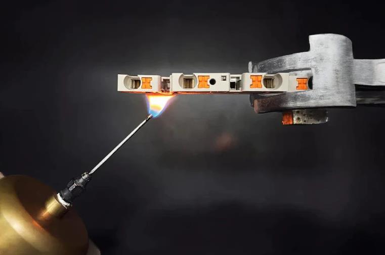
4. The test terminal is higher than the industry standard to ensure high performance and high quality.
The quality of the terminal products is guaranteed by the supplier using laboratory facilities that have passed UL and VDE witness testing and certification. Wiring technology and termination products must be strictly tested in accordance with UL 1059 and IEC 60947-7 standards. These tests may include placing the product in an oven at 70°C to 105°C for 7 hours to 7 days depending on the test, and confirming that heating will not cause cracking, softening, deformation or melting. Not only must the physical appearance be maintained, but also the electrical characteristics must be maintained. Another important test series uses various types and durations of salt spray to determine the long-term corrosion resistance of products.
Some manufacturers even surpassed industry standards and created accelerated weathering tests to simulate harsh conditions and confirm long product life. They choose high-performance materials such as PA66 plastic, and have accumulated deep experience in high-precision injection molding processes to control all variables and meet end users’ needs for miniaturized products that maintain all ratings.
Electrical terminal blocks are a basic component, but they deserve attention because they constitute the main installation interface for electrical equipment and wires. Conventional screw-type terminals are also well known. Advanced technologies such as PID and multi-level terminal blocks make designing, manufacturing, and servicing equipment faster and easier, while saving a lot of valuable control panel space.


