
 logo
logo - Home
- Product
- News
- Solutionlist
- About Us
- Contact Us

Do Better Performances in Demanding Duties


General
Yueqing Aiso TBBX type high voltage fiexd reactive compensation complete set/ deviceswitchgear panel(hereinafter referred to as the device) is suitable for 6-35kV AC power system with frequency of 50Hz. It is mainly used in power system to adjust bus voltage and reactive power, improve power factor, improve voltage quality and reduce network loss.
We can provide the most appropriate, the most reasonable solution according to the customer's requirements. As long as you tell us your requirements or drawings, we can provide a complete solution. And the main components, according to your requirements, choose the brand, Or we can provide cost-effective components to reduce your purchase cost.

Executive standards
GB50227-2008 “Code for design of shunt capacitor device
JB/T7111-1993 “High voltage shunt capacitor device”
JB/T10557-2006 “High voltage reactive local compensation device”
DL/T 604-1996 “Ordering technical conditions for high voltage shunt capacitors”
Main technical performance index
1.Capacitance deviation
1.1The difference between the actual capacitance and the rated capacitance of the device is within the range of 0- +5% of the rated capacitance. The standard is higher than other factories
1.2The ratio of the maximum to the minimum capacitance between any two line terminals of the device shall not exceed 1.02.
2.Inductance deviation
2.1Under rated current, the allowable deviation of reactance value is 0~+5%.
2.2The reactance value of each phase shall not exceed ± 2% of the average value of three phases.
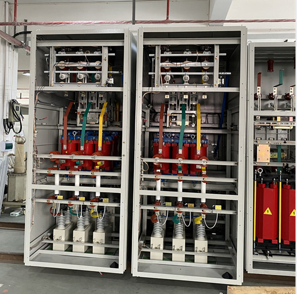
Structure and working principle
1.The device is a cabinet structure or a frame structure, which can switch the capacitor bank manually, and can be equipped with voltage and reactive power automatic controller to auto -matically switch the capacitor bank.
2.The cabinet structure device consists of an incoming isolating switchgear, a series reactor cabinet, a shunt capacitor cabinet and a connected bus. The capacitor cabinet can determine the number of cabinets according to the compensation capacity and the setting scheme, which is generally composed of multiple cabinets. The cabinet body is made of high-quality cold -rolled steel plate bending welding or aluminum-zinc plate bending assembly.
3.Structure layout: when the rated capacity of a single capacitor is 30 kilowatts, the capacitor bank is composed of three-layer (single) double-row structure, when the rated capacity is more than 100 kilowatts, two-layer (single) double-row structure, and when the rated capacity is more than 200 kilowatts, single-layer (single) double-row structure.
4.Frame structure device is composed of disconnector frame, dry air co re reactor, shunt capacitor frame and fence. It includes zinc oxide arrester, shunt capacitor, single protective fuse, fully sealed discharge coil, post insulator, copper (aluminum) bus bar and metal frame.
•The capacitor set is shelved on the metal frame, and the connection bus and pillar insulators are combined to form a primary circuit according to the set connection mode.
•The structure of capacitor bank is usually assembled type, with firm and stable structure, saving steel and convenient installation and transportation.
•The installation forms of capacitor can be divided into single row three layer type, double row single layer type and double layer double row structure.
•Each phase capacitor is usually connected in parallel and then in series. The surface of metal frame is hot-dip galvanized or sprayed with plastic.
•Fence (1.8m high) can be set around the whole device as required. The fence surface is sprayed with plastic. The frame material is made of high quality profiles. See Fig. 11-Fig. 17 for the outline and structural view.
5.Selection of series reactor
The series reactors installed on the neutral side generally choose the dry core reactor; the series reactors installed on the power side generally choose the air-core reactor, which can be stacked in three phases or installed in font.
6.Secondary protection and control
The capacitor bank adopts microcomputer capacitor protection monitoring device, which is installed on the fore high-voltage switchgear. It has two control modes: manual and remote automatic control, and the two block each other.
For the capacitor bank which needs automatic switching control, the voltage and reactive power automatic control device or power factor controller is used to automatically switch the capacitor bank through sampling, logic analysis and instruction switching switch. The controller carries RS232 or RS485 communication interface, which can be connected with other monitoring equipment in the substation to form an integrated substation automation system to meet the requirements of various operation and management modes such as unattended or undermanned substation and centralized control.
7.Interlock requirement
The incoming cabinet is equipped with grounding switch and circuit breaker mechanical inter -locking and electrical interlocking, and each capacitor is provided with electromagnetic lock and door lock, playing the role of safety protection. When all the cabinet doors are not allowed to close or open at will during operation, the main switch will trip immediately; for the frame structure, the user must install a mechanical coding lock on the operating mechanism of the isolating switch in the capacitor device and the fence door to form an miss operation blocking with the fore circuit breaker. The fence door must be locked before operation and must not be opened during operation, to strictly prevent the occurrence of all kinds of misoperation.

Are you looking for support or purchase information?
Contact us


